Link Engine Management
Link G4X MX5Link MX5NB1X ECU
Link G4X MX5Link MX5NB1X ECU
Couldn't load pickup availability
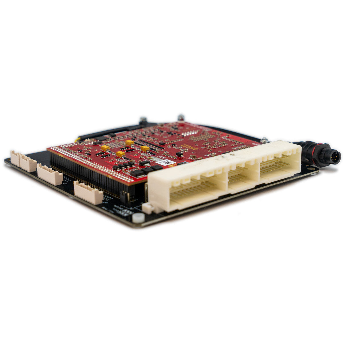
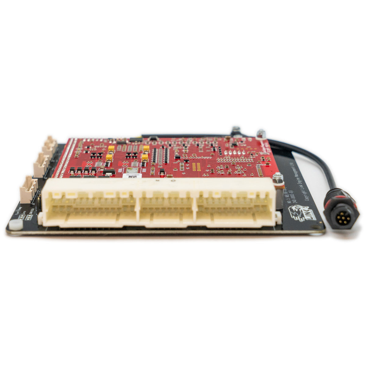
The Link G4X MX5Link MX5NB1X ECU is a direct-fit engine management system designed for pre-facelift Mazda MX5 NB models with the non-VVT 1.8L engine. It installs into the factory ECU location and connects directly to the OEM wiring loom on supported vehicles.
This ECU is intended for manual transmission vehicles only and supports most factory systems while providing advanced tuning capability through the G4X platform.
Important: Manual transmission only. Designed for pre-facelift MX5 NB (1998–2000) with 3-plug ECU and non-VVT 1.8L engine. Please confirm your ECU connector matches the header shown in the product images before purchase.
Engine Control Capability
- Designed for non-VVT 1.8L MX5 NB engines
- Sequential fuel injection
- Digital triggering using OEM patterns
- Staged injection support
- Knock control with windowing
Hardware and Platform
- Direct plug-in installation using factory ECU enclosure
- Includes onboard 7 bar MAP sensor
- Continuous onboard barometric correction
- USB tuning connection
- 512 MB onboard data logging
Vehicle Compatibility
- Mazda MX5 NB pre-facelift (1998–2000)
- Non-VVT 1.8L engine
- 3-plug ECU
- Manual transmission only
G4X Plug-In Key Features
- Up to 6D fuel and ignition mapping
- Sequential fuel delivery
- OEM idle control supported
- 5D boost control with three switchable tables
- Launch control, anti lag, and flat shift
- Individual cylinder fuel and ignition correction
- Gear-based fuel, ignition, and boost compensation
- QuickTune automated fuel tuning
- Selectable dual fuel, ignition, and boost maps
- CAN communication support
I/O Expansion
This ECU features dedicated expansion connectors for additional inputs and outputs.
Expansion Connector 1
- Pin 1 – Analogue Temperature 4
- Pin 2 – Analogue Temperature 3
- Pin 3 – DI10
- Pin 4 – DI9
- Pin 5 – DI8
- Pin 6 – DI7
- Pin 7 – IGN4
- Pin 8 – IGN3
E-Throttle Connector
- Pin 1 – Signal Ground
- Pin 2 – +5V Sensor Supply
- Pin 3 – Analogue Voltage 12
- Pin 4 – Analogue Voltage 11
- Pin 5 – Analogue Voltage 10
- Pin 6 – Analogue Voltage 9
- Pin 7 – Aux 10
- Pin 8 – Aux 9
CAN note: This Plug-In uses a 4-pin powered CAN connector and cannot use the older CANPCB cable. Use the CANJST4 cable (Link PN 101-0198) for CAN devices. This port provides CAN communication plus protected 12V power and ground.
Downloads and Resources